Setting Up Your Pi & Assembling your device

Time to bring out your soldering iron.

Quick Summary Video

Step 1: Booting Up Your Pi

First let's install your Pi's operating system and ensure it can boot on up.

  • First plug in your Micro SD card into your PC, if prompted to format the drive in anyway simply ignore it.
  • Next go to: https://www.raspberrypi.org/software/ and then download the "Raspberry Pi Imager" tool for your operating system.
  • Once downloaded, install the software, following the instructions on screen. Then launch the Raspberry Pi Imager program on your computer. You should hopefully then see a screen similar to the below:
A Screenshot of Raspberry Pi Imager
  • Then click on "Choose OS", on the next screen click on "Raspberry Pi OS (other), Other Raspberry Pi OS based Images". Then click on "Raspberry Pi OS Lite (32-bit)". It is very important that you have selected the Lite version of the operating system.
  • Once you have selected the operating system, click "Choose SD Card" and find the SD Card plugged into your device.
  • Next click on the "Settings Cog" in the bottom right hand corner to open up the advanced options screen shown below:
A Screenshot of Raspberry Pi Imager
  • In here we'll need to configure several settings:
  • First check that the hostname is still set to "raspberrypi"
  • Toggle on, SSH, and ensure use password authentication is set.
  • Toggle on "set username and password", set the username to "display" and the password to one of your choice - remember this for later.
  • Toggle on "configure wireless LAN", set the SSID to your WIFI's network name, then set the password of your WIFI so your Pi can connect to your internet. If you have separated 2GHhz and 5GHz WIFI networks always use the details of your 2GHz network.
  • Toggle on "Set locale settings" ensure Europe/London and gb keyboard layout is all set.
  • Then click "Save" to set these values, now we're ready to write to our SD card, click on "Write". You may be reminded any existing data on the card will be deleted, simply confirm you're happy with this.
  • Once completed you're safe to remove the Micro SD card from your PC, put it into your Pi and plug in the power to turn it; see diagram in step 2 on where to plug in the power lead.
  • The first time you're Pi is booting up it can take up to 4~min, if you were to connect it into a monitor during the first time boot up you'd see it restarting several times, this is usual.
  • While we wait for it to turn on go to: https://www.putty.org/ from there follow the links to download "puTTY" and install it onto your computer. This will allow us to SSH remote into our Pi (wirelessly control it).
  • Once you have downloaded and installed puTTY and waited up-to 4 min for your Pi to turn on fully, launch puTTY. You should see a program as shown below:
Screenshot of Putty Software settings.
  • First make sure that your computer and your Pi are both connected to the same network. Then enter into the host-name box "raspberrypi". Check that the port number is set to 22  and that the connection type is on SSH. If all these values are correct click the "open" button.
  • Hopefully putty can find your Pi and a security alert might pop up asking are you sure you trust this device; simply click "yes". A console window should then appear asking for your username.
  • The username is: display
  • The password is the value you set previously when you installed the OS to the SD card.
  • While entering in the password your input will not be outputted to screen this is normal. Once both username and password are entered you should hopefully be logged into your pi fully. If not see the troubleshooting page for more information and an alternative approach.

Step 2: Configuring Your Pi

Now you need to turn on a few features of your Pi to continue.

  • Now you have logged into your Pi in the puTTY console window type in the command:
  • sudo raspi-config
Screenshot of initial Pi console window.
  • When you click enter a new screen should appear, as shown below.
Screenshot of the rasp-config window.
  • Then go to " Interfacing Options ". On the next screen click on " P4 SPI" or "I4 SPIR" and be sure to enable SPI connections.
  • Then exit from this menu by pressing the "esc" key a few times till you return to the console. Now we will check for any updates for your Pi by entering in the command.
  • sudo apt update  -y
  • Once finished your cursor should be flashing green again, if successful write the following command below.
  • sudo apt full-upgrade -y
  • Once the command has finished, we need to turn off the Pi to wire it up. Normally you can simply unplug the device, as we have made some system changes to be safe shutdown properly typing the command "sudo shutdown -h now" and then unplug it after 30 seconds.

Step 3: Wiring Everything Up

The first thing you need to do is connect the Pi Zero W with your OLED display.

To connect the display to your Pi please refer to both the diagram and the table below, taking extra care to make sure you have both in the same orientation as the shown so not to wire up the device incorrectly. Incorrect wiring up can cause permanent damage to the display and/or the Pi. Also do not attempt to wire up the display while the Pi is turned on. If you have opted for a header-less display and Pi you will now need to bring out your soldering iron. If you have opted for a headered display you just simply need to push the wires into the correct pins.


OLED Display Pins : 1,7,8,9,10,11,12 and 13 can be connected to the Pi Zero Pins: 6, 9, 14, 20, 25, 30, 34 and 39 in any combination.

Those display pins simply need to be connected to any Pi ground pin. The Diagram below will show one possible combination. Where all OLED Pins are connected to one Pi Zero Pin 6, but if you want you can connect one OLED pin to one Pi pin of your choosing.
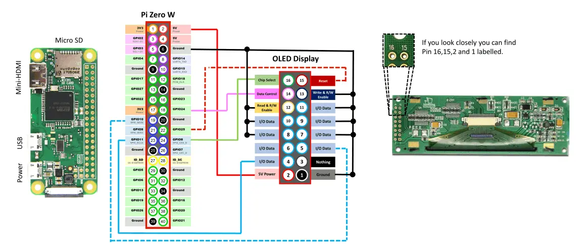
The wiring schematic for connecting up the Pi and Display.
The below table should be used in adjacent to the diagram above, please double and triply check your wiring. This is one of the main areas for fault to occur.
Pi Zero Pin Number OLED Display Pin Number
2 2
6, 9, 14,20, 25, 30, 34 and 39 1,7,8,9,10,11,12 and 13
18 14
19 5
22 15
23 4
24 16

Stage 1 Completed!

Awesome, you've setup and wired your Pi, now let's install the software!

© Copyright 2023 Jonathan Foot - All Rights Reserved

Cookie Policy  • Terms & Conditions Contact Me